<<<<<<< TWO ....... STROKE ....... MIX ....... RATIOS >>>>>>>
RD350LC YPVS........ 1983 ...........31K...................31K000101-015000 .......................nose
fairing,bellypan
RD350LC YPVS........ 1984.............31K..................31K028101-044000 .......................nose
fairing, bellypan
RD350NI ...................1985..............1JF...................31K077101-085000........................no
fairing or bellypan
RD350FI ....................1985.............57V...................31K053101-072000........................full
fairing
RD350NII...................1986.............1WA.................1WT005101-010000......................p/jet
carbs bean can pipes "no fairing"
RD350FII...................1986.............1WT.................1WT000101-004923.........................full
fairing
RD350FII....................1988-92 .......1WT.................1WT015101-onwards.......................full
fairing
RD350R .....................1992-on ........1CE..................4CE000101-onwards.......................full
fairing twin light "made in brazil"
MODEL
YEAR
PREFIX
CHASSIS / ENGINE No*
COSMETICS
Some
people don’t know which model YPVS they own. This can be disastrous
when ordering parts through the post .
I hope the following info will help some one
These are the bhp readings given by Yamaha. The mpg will go down by 10 when ridden properly, more when tuned. It has to be said that if you dyno your bike, you won't get the HP shown here. The true HP is a good bit less in many cases.
RD 123 LC ...... 2-stroke ...... single ..... 12bhp ...... 210lb ...... 70mpg ...... 75mph
RD 247 LC ...... 2-stroke ....... twin ....... 30bhp ...... 310lb ...... 30mpg ...... 100mph
RD 347 LC ...... 2-stroke ....... twin ....... 43bhp ...... 320lb ...... 30mpg ...... 115mph
YPVS 347 31K . 2-stroke ....... twin ....... 57bhp ...... 320lb ...... 35mpg ...... 120mph
YPVS 347 F2 .... 2-stroke ....... twin ....... 62bhp ...... 3501b ...... 35mpg ...... 125mph
YPVS 499 ........ 2-stroke ....... V4 ...... 77bhp ...... 392lb .... 30mpg ...... 135mph
Fuel / oil ratio
Helpful hints Before building the top end
Make sure all the old gasket has been removed from the bottom of the barrels
and your casings using a stanly knife blade them a wipe with wet and dry .Always
check to see if the ports have been radiuses as a lot of places who do re-bores
don’t radius the ports. " This is cleening up the sharp bits"
Always give the barrels a good clean out. As there might be some swarf left
over from the re-bore stuck in the transfer ports that could do some damage!
Don’t forget to put 2 stroke oil the bores and the pistons before assembly
of the top end. Common sense I know, but you would be surprised at how many
people don’t.
Running In
Allow the motor to warm up without revving the balls out of it!! When riding don’t be scared to let the revs rise to 6,000rpm in the first few gears. Then drop back down to around 4,000rpm for around 150 miles dont let it go in the band . Then Tack it up to 8,000rpm droping back to 6,000 for a further 150 , the pistons should have been bedded in by 300 miles. If the engine has new bearings, in the crank or gearbox, then no special treatment is needed as bearing don’t need to be run in.
If this was the case then you’d have to run your wheels in every time you replaced the wheel bearings!
To Keep your LC and valves Running Well
Always run with semi or fully synthetic 2 smoke oil. I use MOTUL 600. Always
maintain the air filters if fitted. Check and lube the chain often. I use
a chain wax, it doesn't spray.
If you want more performance, don't be sucked into running with separate air
filters because the standard airbox will give you more performance on a road
engine. Many people just remove the filter inside or the inlet tube. If you're
going to run expansion chambers, always jet correctly by starting big and
moving down. Standard jets will probably cause a seize or meltdown. A good
starting point is 2 sizes up on standard.
On a twin… If the barrels have a diferent tune to each other then you
MUST get them matched up or the crank will be stressed and out of balance
and will blow. There's no need to panic if one bore is just .25 mm bigger
than another, this is only a quarter of an mm and won't be any problem, but
any bigger could put the crank out of balance. It's always better to run both
barrels the same size.
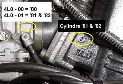
During 1980, the RD350LC had problems with exhaust studs breaking, exhaust pipes craking, acceleration problems (mid-range misfire) and too rich oil pump. These pipes breaking were the result of engine movments and too fragile pipes.
To resolve these problems, YAMAHA propose during '80 to replace pipes (reinforced) under warranty, new carbs settings and new oil pump setting.
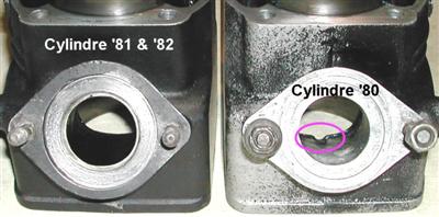
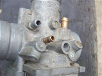
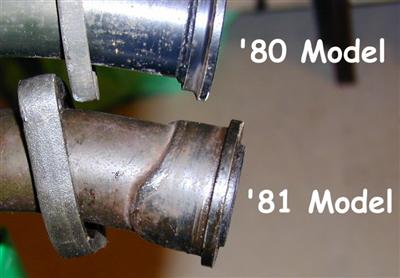
'81 & '82 RD350LC models were sold with the following evolutions: new cylinders, new carbs (stamped 4L0-01 instead of 4L0-00 for the '80 one), new exhaust mounting on cylinder & new pipes (differents from the solution proposed during '80 ), add 2 tie rods fixed to the underside of the crankcases and extending forward to the frame and new red valve . There were 2 types of front brake calipers.
So there was 3 different solutions of exhaust mounting from '80 to '81
Screw the idle adjust screws in till they just touch the slides. To adjust idle RPM, adjust these screws in or out the same amount on each carb to keep the idle slide position balanced.
Float height: Although this adjustment is done with the carbs off the bike, the best way to confirm that it is correct is to attach a clear piece of tubing to the drain/overflow fitting on the bottom of the carb and use it as a sight glass. Again with the bike level on the center stand, connect the tube and hold it up alongside the carb body. With the fuel supply on(prime position?) and the float bowls full, open the float bowl drain screw. The fuel in the bowl will seek it's own level in the clear tube and you can see where it is in the bowl. The fuel supply will make p the ammount sent out into the tube for an accurate level reading in the bowel. It should be within 2MM of where the top of the bowl meets the carb body. This is important as the different circuits draw fuel from different levels in the bowl. If not correct then you must re-bend the tabs on the floats to get it there(float height adjustment in manual).
At this point, if everything is mechanically balanced, you should be able to re-assemble the air intake and any other plumbing and start the bike. The idle will probably be off and require adjustment with the setscrews(remember, both screws at the same time). If you set up the carbs the same as the ones you took off, It should be similar to how it was but it will still require some adjustment and checks before you can declare it safe for the road.
I have covered a lot here, so lets call this phase one. Why don't you crunch on this info and decide if you want to tackle the carb swap yourself or get some local help to do it. It is not especially difficult and if you don't dis-assemble the old carbs, you always have those to fall back to if you run into difficulty.
Phase 2, Oil Pump Check and Adjustment:
Since you don't have the stock pump on, you should probably check the pump output that you do have as this will have a large effect on the life of the engine and on the mixture adjustments on the carb in the final stage. For the first part, you will need to drain the fuel tank and mix up a gallon of 30:1 pre-mix fuel/oil and put that in the fuel tank. Next is to remove both oil lines where they connect to the carbs and route them somewhere where they can both be put into a container and the pump output measured. Plug the oil inlet ports on the carbs, another piece of tubing(vacuum tubing from an auto parts store or model fuel tube works well for this) connecting them together works well.
As I am sure you have noticed, the gear driven pump strokes a plunger, the length of which is controlled by a pully and cable connected to the throttle. Adjust the oil pump cable to the manufacturers specs keeping in mind that the closed throttle position should be with the throttle free play taken up on the throttle to the point where the carb slides are just about to open. Once this is set, with the engine idling on pre-mix, pull the oil cable to its maximum position and make sure the oil lines are completely full of oil. Then let the pump cable return to the minimum position(point where throttle cable slack is taken up and the carb slides would just start to open) and measure the combined oil output from both hoses for 200 strokes of the pump(this takes a while and is a very small amount of oil). The volume should be 0.12CC - 0.19CC.
Next, with the engine SHUT OFF, twist the throttle to its wide open/full throttle position. Note the position of the oil pump pulley, I put a small paint mark on it with bright red model paint and a toothpic near a fixed structure in the oil pump compartment. Once you have marked the full throttle position, Return the throttle to the idle position.
Re-start the engine and with it idling, pull the oil pump cable until the oil pump pulley is at the full throttle position as noted by the mark you made. Measure the pump output for 200 pump strokes. Again, this takes a while to count 200 strokes and the output volume should be between 2.58CC - 2.85CC. As you can see, this is not much oil. I use a small measuring syringe for dispensing children's medicine. I once counted 1000 pump strokes at the pump idle position to get a larger more easily measurable volume.(I set up a fan in front of the radiator to keep the bike cool for this extended run).
If these measurements are good, re-confirm the oil cable adjustment with the throttle free-play taken up. THIS IS IMPORTANT! and WILL affect the mixture adjustments in the next phase. It took me quite a while of scratching my head over inconsistent test results after de-installing/re-installing the carbs several times before I got fanatical about checking this adjustment ANY time I did anything associated with the throttle cable/carb linkages.
Drain the pre-mix fuel and re-connect the oil lines to the carb ports. I always like to confirm that I can blow through these ports into the carb before I re-connect the oil lines. Add some regular fuel to the tank and you are about ready for a test ride to check plug color again
Carb Theory and Adjustment:
For practical purposes, there are 3 basic carb circuits and engine RPM is basically unimportant. What is important is throttle position as this determines which carb section is providing the air/fuel to the engine.
The pilot section: This is from just off idle to around ¼ throttle.
It is the most used section in the carb as the throttle spends 99% of its
time in this region(unless you are racing). Because of this, it is provided
with an infinitely adjustable airscrew and jet system for fine-tuning. The
size of the pilot jet and the setting of the pilot airscrew determine the
pilot airscrew mixture below ¼ throttle.
Needle jet/jet needle section: This is from the ¼ position to around
the ¾ position. This range has adjustment capability by jet and needle
selection and the needle clip position(needle height). The throttle does not
spend much time here but has these adjustments to make for a smooth transition
from pilot to main section when accelerating.
Main Jet Section: This section covers from ¾ to full throttle and is
only really adjustable through main jet change out with emphasis on the widest
throttle position.
It is VERY important that EVERYTHING else is properly set up(carb balance,
throttle free play and oil pump adjustment/delivery volumes) before proceeding
with any carb adjustments.
Since all these sections are additive and the amount of fuel delivered down at low throttle will contribute to the full throttle mix, the best place to start is the pilot section. One adjustment procedure talks about adjusting the idle speed, then adjusting the pilot airscrew for highest idle speed then re-adjusting the idle back down and trying again for a peak idle speed using the airscrew until the highest peak is found. I have used this method on several single cylinder engines but have NEVER been able to get it to work properly on a 2 cylinder RZ/RD. I think the second carb and crossover tube have something to do with it. The pilot circuit doesn't really come into play until the engine is placed under load. The idle circuit is fixed with it's only variable being the height of the slide as adjusted by the idle setscrew. On the RZ, I have been able to adjust the airscrew so far out that the engine dies as soon as I try to open the throttle and pull away, but the bike will still start and idle perfectly on the first kick with the throttle closed.
The method I found that works the best is to start the engine and warm it up to normal temp. With the pilot airscrews set 1 ½ turns out on both carbs, try and pull away in 1st gear from a stop on a level roadway or parking lot. Ideally the engine should pull you away nice and smooth. Make a small adjustment to both airscrews, say around 1/8 turn, either open or closed and try and start off again. Was it better or worse than the first try? If better, move the airscrews another 1/8 turn in the same direction and try again. If worse, return the screws to the original position(1 ½ turns out) and go 1/8 turn in the opposite direction. Keep doing this trial and error method past the point where the best pull-away is achieved and a decrease in performance is noted. Don't let the engine get too warm, as this will affect results.
Remember, the pilot airscrew controls the air being mixed with the fuel from the pilot jet. If you have to go below 1 full turn (airscrew in = richer) from the fully closed position to get best pull-away performance, your pilot jet is too small and you need to upjet. If you have to go above 2 full turns out(airscrew out =leaner) for best performance your pilot jet is too large(passing too much fuel) and you need to go to a smaller pilot jet. Below 1 turn or above 2 turns the pilot airscrew is no longer linear and adjustments are unpredictable. Above 3 turns there is no effect at all. Ideally you want a pilot jet that gives the best pull-away performance with the airscrew near 1 ½ turns out. Once you have it in this area with 1/8 turn adjustments, try and see if you can get it any more refined with smaller adjustments. Then try pulling away up a slight incline(greater load) and see if you can refine it any more
Once you have the best pull-away performance, go for a ride with new plugs and see what kind of color you get on them from a cruising "plug chop"(like the tests you posted pictures of, level road, up to highway speed using as low a throttle as possible). Here is where you can make small adjustments to the airscrew settings to get the desired color on a cruising chop. If your carbs are mechanically in good balance, small changes to one carb or the other can get the same color on both plugs. I have yet to see a factory multi cylinder carb pair with the exact same setting on all carbs. My own RZ factory settings were different nearly 1/8 turn from one carb to the other.
Once you have the pilot section ironed out, the next step up is the needle jet/jet needle. If the flow thru the engine has not been radically altered(porting, squish ect) then you will probably be fine with the stock needle and jet combo and only need to adjust needle height. Your needle may have 5 different clip positions (the US RZ only has a single position). What you are looking for in this section is a smooth progression from the pilot section into the midrange section. If the needle is too low(lean), as you reach the top of the pilot section(around ¼ throttle) the engine will start to bog(lack horsepower or hesitate) and perhaps even knock or ping if the case is extreme enough. Conversely, a too high needle position(rich) will also result in an engine bog but with a dull/flat engine sound.
The center needle position will probably work OK for your bike but you can try moving the needle up/down to see how it performs. If it seems better in a particular direction, you can also use small/thin washers as shims under the clip to refine the height of the needle at less than full clip positions. I use washers to adjust the needle on my RZ. Any time you do anything that involves the throttle cable, like removing the tops and slides to change the needle height, re-confirm the mechanical balance and carp/throttle/oil pump adjustment. Any changes in these will effect your results and make you wonder why you didn't get the results you expected(plug indication is richer from increased oil maladjustment when you expected leaner because you just put in smaller jets/leaned out airscrew or needle).
Once you have a smooth transition to mid throttle, You can check this mix by doing ½ throttle plug chops, accelerating through the gears on a new set of plugs. Warm up the bike by riding to your test road(long, straight, level or slightly uphill) Stop the bike and put in new plugs. Get ready for the test run, put the bike in first gear. Start the engine and pull away and start accelerating immediately, avoiding idle as much as possible so it doesn't skew your results. Get the throttle open to ½ as quickly as possible and keep it there while you accelerate, closing it only briefly to shift(Close throttle, shift and right back to ½ throttle). The goal here is to keep the throttle at the position being evaluated for as much of the run as possible. Accelerate like this for as far as your gears, nerve or the law will allow then hit the kill switch and pull in the clutch to get the engine stopped as quickly as possible and coast the bike to a stop. Remove the plugs and check your results.
You should have some indication of color on the plugs(may take a second or third run to add up). You should NOT hear any knocking or pinging under these ½ throttle load tests. If you do, you may want to re-evaluate the needle position and raise it some(richen) so you can get a smooth test in and see some color on the plugs. A little darker here is not necessarily a bad thing. This is an area that is usually passed through and not stayed in so a little on the rich side will help keep your engine healthy. Remember, too rich only really fouls plugs. Too Lean and you eat pistons and or seize the engine. (In my youth, I miss-timed a R5B too far on the advanced side causing slight pre-ignition and detonation same as a lean burn condition and melted a thumb-sized hole in the top of each piston while cruising down the highway).
Once you have the pilot and mid section sorted, it is on to the Main section. The main jet section is mainly done with the plug chop method I described above except that you are accelerating with the throttle wide open as much as possible. If the jetting is really off either way, you will feel it as you try and accelerate. The area above ¼ just wont feel any more powerful or it may even bog down. While you are doing your midrange or pilot setups, you can completely remove the main jets and try to run up above ¾ throttle(you won't notice they are gone until then) and see what a way too rich main jet would feel like.
The full throttle plug chops can be a little tricky sometimes as if everything
is balanced, the transition through pilot and midrange are smooth and you
are making good power, the front wheel may want to come off the ground in
the lower gears. You can back off the throttle just slightly to keep the wheel
on the ground till 3rd gear and above. As before, any knocking/pinging noted
under wide open throttle acceleration is VERY bad. Again, the result should
be some visible color on the plug(again may take a run or two to show). A
little darker up here is not really going to affect your useable power but
will affect the life of your engine. Remember, the throttle doesn't spend
a lot of time up here, but the times it does are high stress. A little extra
fuel for cooling is not a bad thing.
That is everything you'll ever need to know .
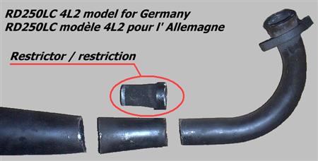
With the advent of so many German LC's making there way to the UK . I was sent this by a member of the forum who thourght it mite be of some intorest .
It shows the Restrictor in the pipe you will need to remove if you want full power from your LC.
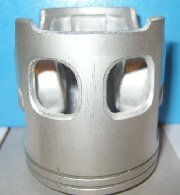
If you are reboring your LC the only pistons that you can get theys days are YPVS ones. They are better anyway with biger windows then the old LC pistons of old.
However you will need to remove the small tab found on the bottom scurt in the middle of the piston between the windows. The pison shown has had the tab removed.
Some people don't remove it and get away with it, others do not and it catches so you may as well remove to be on the safe side file smooth ater removing it.
This is an attempt at a translation of "Martin Kieltsch RD Bible. For experimental use only. I am not responsible if this information is incorrect because of any error. The following info was given to me from some one of the FORUM http://rdlccrazy.proboards.com/. I have not tryed this my self but beleve it to be correct.
The YPVS series have three different stators, rotors and CDI units
83-84 RZ350
The CDI of the first two years of construction (' 83 and ' 84) carries the marking 29 K-50. The 29K-50 CDI has a square four-fold plug, a t-shaped connector for the load coil (brown, green and red) , a two-fold plug for the Pick UP and a black ground wire. One can recognize the stator (marking ÇY) by the appearance of the load coils. This stator has a thicker coil in the center and on the right of and on the left of two smaller, which are curved like horns. The stator is marked ÇY and/or 2CY. It has two drillings and two long holes. The rotor has the marking 29L - 50
85 RZ350The 1985 31K has changed Stator and CDI. The CDI is marked 52 Y-50. The 52 Y-50 CDI has also only 8 connections (the other two to have 9). This CDI is missing the black-and-white cable, which serves to turn the engine off by the kill switch. The 85 stator is marked ÈZ or 8DX. The stator has two somewhat thicker load coils. Safe distinguisher of the 85 stator is the red-white cable at the load coil, which is always red with both other stators! A further indication is the missing connector for the "load coil", which into three individual plugs (brown, green and red-white) is divided. The Rotor has the marking 51L - 50 .86-95 RZ/RD350
The 86-95 CDI are marked 1UA - 50. The Stator looks outwardly like the ' 85 stator,but it has different plugs. A square four-fold plug, a flat connector for the load coil (brown, green and red) , a flat two-fold plug for the Pick UP and a black ground wire. The marking on the stator is 1FX. The rotor may posess the markings 1UA, -50,VCD 88,(1FY).
Combinations:The 86+ Stator functions only with the suitable rotor(VCD 88);The 86+ 1UA - 50 CDI will work without changes with a 85 31K bike. . The black white cable can remain free.
One can also use the 1UA-50 CDI with the 83/'84 31K stator(ÇY/2CY). In addition one must change the plugs going by that the cables "red" and "green" of the load coil must be exchanged . If one connects same colors, she does not function!
One can use the 85 (52Y- 50) CDI with the 84 or 86+ models. To connect an 85 cdi to an 86+ one connects the same colors and also put the black-and-white cable of the wiring harness to the black-yellow cable of the CDI. A second possibility is, black-and-white cables to the red cable to the CDI to also put (it functions both).To use an 85(52Y- 50) CDI on an 83-84 31K system you must exchange the colors red and green and put additionally the black-and-white cable of the wiring harness also to the black-yellow cable of the CDI. A second possibility is again to also put the black-and-white cable to the red cable to the CDI.
If the black-and-white cable remains free, one cannot turn the engine off
Chart Cipher:
The 84 29K- 50 CDI will work with an 84 stator and an 85 rotor.
The 85 52Y- 50 CDI will work with with the 84 rotor and 84 stator if you exchange R/Gr , S/W at S/G
The 85 52Y- 50 CDI will work with 85 rotor with 84 stator if you exchangeR/Gr , S/W at S/G
The 85 52Y- 50 CDI will work with 84 rotor with an 85 stator.
The 85 52Y- 50 CDI will work with an 86+ rotor with an 86+ Stator if you S/W at S/G
The 86+ 1UA- 50 CDI will work with an 84 rotor and an 84 stator if youexchange R/Gr .
The 86+ 1UA- 50 CDI will work with an with an 85 rotor with an 84 stator if you exchange R/Gr
The 86+ 1UA- 50 CDI will work with an 84 rotor with an 85 stator
The 86+ 1UA- 50 CDI will work with an 85 rotor and an 85 stator
The only thing I can't figure is what "S/W at S/G" stands for. Stripe?.....hmmmm
s/w = black/white
s/g = black/yellow
There is at least 3 CDI types on YPVS 350 Models:
29K-50 for 31K 83-84
52Y-50 for 57V/1JF 85-86
1UA-50 for 1WT / 1UA / 3DH1
???? for 4CE6 (RD350R).
CDI Troubleshooting:
CDI theory
The CDI ignition takes a pulsed current generated by the low or high-speed
charge coil (depending on engine RPM) and charges a capacitor. This stored
charge is then discharged into the primary winding of the ignition coil causing
the plugs to spark (both at once). The timing of this discharge to the coil
is triggered by the arrival of a small electrical pulse generated by the pickup
coil and electronically delayed to occur at the proper time by circuits internal
to the CDI module. The ignition, engine run and side stand control unit provide
a circuit to ground to "kill" the ignition. There is an old saying
"garbage in equals garbage out" If any of these signals are missing
or a short circuit to ground occurs in the "kill" circuit, the CDI
will be unable to function properly.
Engine mechanical:
Suspected ignition problems are sometimes not that at all but other engine
mechanical failures so before we test electricals lets first check the following
basic items:
1. Engine has good compression and the difference between cylinders is small.
Upper 90's for PSI is good for a cold engine (5 kicks with throttle wide open).
2. Carbs are mechanically balanced.
3. Check auto lube pump adjustment
4. Install a set of NEW plugs. The secondary winding of the ignition coil
is attached to both plugs. In order to complete the circuit the current must
flow down one plug wire to the plug, jump the gap, go thru the engine cylinder
head to the other plug, jump that gap then go back up the wire to the coil.
If you interrupt this circuit, neither plug will fire. If you do experience
one plug sparking without the other, the circuit is being completed another
way, perhaps through the plug wire insulation to the frame or perhaps internal
to the ignition coil to the metal core which is bolted to the frame.
Engine electrical:
The RZ electrical connectors can corrode pretty bad. The engine vibration
helps to maintain good contact but a bike that has set for a while can develop
electrical "ghosts" quite easily. So lets start by separating, inspecting
and re connecting all the electrical connections associated with the ignition
system. When that is completed take the following readings. The following
readings can be taken using the standard test leads that come with most digital
volt ohmmeters. The RZ electrical system is connected together with molded
nylon "molex" or "spaid" connectors. All the initial readings
are taken with the circuit under their normal electrical load. This means
that all the connectors are connected and you take the reading by sliding
the test probe tip into the molded connector alongside the proper colored
wire until it makes contact with the metal portion of the electrical connector.
You need a digital voltmeter as the delay in the needle reaction of an analog
meter might miss some of these very small signals
1. On the CDI bundle find the connector with
the black wire with a white stripe running along it. Put the red test lead
in along side this wire. Hold the black lead against the bare metal of a head
bolt. Set the meter to read resistance. With the kickstand up, engine in neutral,
the kill switch set to run and the ignition key to on you should see greater
than 30K OHMS of resistance. If you turn off the key or kill switch the resistance
should decrease to near 0.
ALL OF THE FOLLOWING READINGS ARE TAKEN DURING 5 RAPID KICKS! The object is to keep the engine rotating long enough for the digital meter to sample the signal and display a reading. This is easiest with the spark plugs removed, the plug wires connected to the plugs and the plug body connected to ground on the engine case to complete the circuit. What also works well is to tape the metal bodies of 2 spark plugs together, with the insulators pointing away from each other. Attach the spark plug wires to these and this will also complete the coil secondary circuit.
2. On the end of the CDI wiring harness you
will find a 3-wire connector that has a brown, red and green wire. Slide your
black probe in beside the brown wire and the red probe in beside the green
wire. This is your low speed winding. Set the meter to read AC volts, turn
on the ignition and kick the machine over 5 times quickly. You should see,
while kicking, a reading of 25 Volts AC.
3. Now move the red test lead to the red wire
(measuring brown to red) this is the high speed winding kick over the machine
with the ignition on and you should see 4.5 Volts AC.
4. On the CDI bundle there is a 2-wire connector
with a white with red stripe wire and a white with green stripe wire. This
is your pickup coil connector. Slide your test leads in beside these 2 wires.
When you kick the starter rapidly you should see 0.3 Volts AC
5. On the CDI bundle there is a 2-wire connector
with an orange wire and a black wire. Slide the meter probes in beside these
wires. This is the CDI output to the ignition coil primary winding.
When the starter is kicked rapidly, you should see 0.4 Volts AC.
If any of these voltages are missing one of 2 things is happening. Either
the source device is not generating the signal or the destination device is
shorted and the signal is being loaded down. If one of the signals is missing,
separate the electrical connector for that signal (electrically unload it)
and connect your meter to the source side and repeat the test. Here are the
unloaded readings for the above listed signals
2. Low speed charge coil 50 Volts AC unloaded
3. High speed charge coil 4.5 Volts AC unloaded
4. Pickup coil 0.3 Volts AC unloaded
5. CDI output 24 Volts AC unloaded
In the case of signals 2,3 and 4 if the loaded test is bad and the unloaded
test is good do a resistance test of the source device. The low speed coil
(test 2) should read 225 ohms (or 133 ohms depending on engine type). The
high-speed coil (test 3) should read 5.3 ohms and the pickup coil (test 4)
should read 115 ohms. If the resistance check is good the CDI is most likely
at fault.
In case the signal 5 load test is bad and the unloaded test is good, measure
the resistance of the ignition coil primary winding. The primary winding resistance
is around 0.33 ohms. If it is OK then the CDI is most likely at fault.
If all the above readings are good then check the secondary winding of the
ignition coil, the measurement from one plug cap to the other should be about
23K ohms. The plug caps themselves "screw" (twist counterclockwise)
off of the plug wires each plug cap should read about 10K ohm when measured
by itself. The coil and plug wires alone should read 3.5K ohms. It is possible
for the coil secondary to be breaking down under high voltage but measure
just fine with the ohmmeter. If you are getting the proper signal on the black
and orange wire to the coil with no spark out into NEW plugs, then the coil
is probably at fault. I had this happen intermittently for about a year, I
finally found it by connecting up a meter to the black and orange wires and
taping it to the tank where I could see it. The next time the bike quit, while
I was coasting in gear the input voltage was still there with no spark out,
Good in, garbage out. told me it was the coil. One final word of caution.
DO NOT ATTEMPT TO MEASURE THE OUTPUT SPARK VOLTAGE FROM THE IGNITION COIL!
IT WILL DESTROY THE METER!